

Weather Forecast
Your own localised forecast
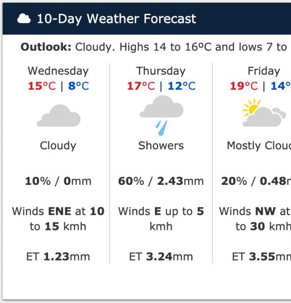
Localised weather forecasts brought to you by Harvest and the IBM Weather Company.
The forecast is specific to your location as a 4 km square section in the global IBM grid - each square having its own forecast. IBM use some of the worlds most powerful supercomputers to analyse and process the data from weather satellites and ground stations to produce quality localised weather forecasts.
The forecasts give detailed hourly predictions for the next ten days. The forecast can be displayed on the Harvest Data Portal or your Harvest Web App.
An add-on option is the forecast of Potential Evapotranspiration (PET) for the next ten days which can assist in irrigation decisions.
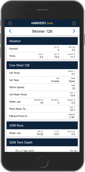
Harvest Web App
Your data where you need it
The Harvest web app is designed to display your data in a mobile friendly format. Each web app is individually setup and customised by Harvest staff to show the things you want to see in the order you want. You won't find it on an app store, it is located at app.harvest.com. To see the live demo login with username 'demo' and password 'demo'. If you are interested in getting a web app for your own Harvest site please contact us.